

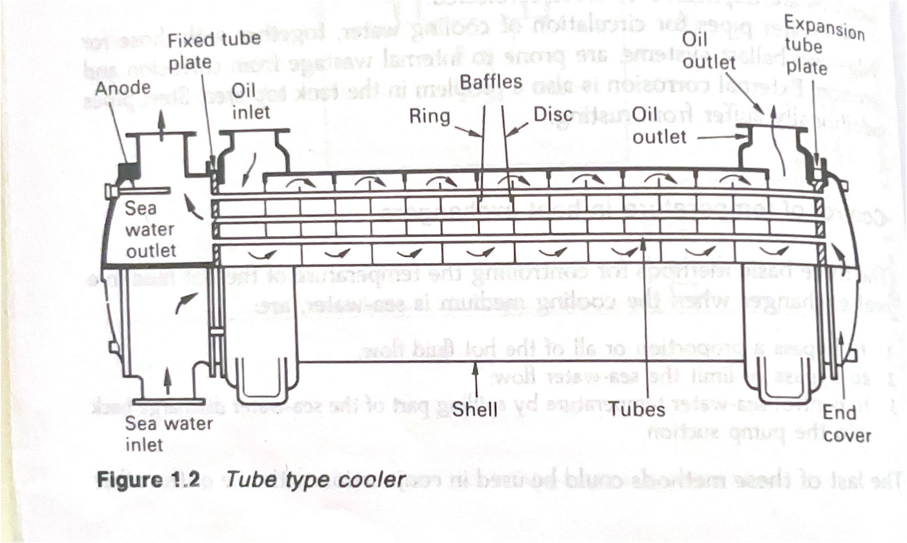
Shell and tube heat exchangers for engine cooling water and lubricating oil cooling have traditionally been circulated with sea water. The sea water is in contact with the inside of the tubes, tube plates and water boxes.
A two-pass flow is shown in the diagram but straight flow is common in small coolers. The oil or water being cooled is in contact with the outside of the tubes and the shell of the cooler.
Baffles direct the liquid across the tubes as it flows through the cooler. The baffles also support the tubes and form with them a structure which is referred to as the tube stack.
The usual method of securing the tubes in the tube plates is to roll-expand them.
500 Tubes of aluminium brass (76% copper; 22% zinc; 2% aluminium) are commonly employed and the successful use of this material has apparently depended on the presence of a protective film of iron ions, formed along the tube length, by corrosion of iron in the system.
Unprotected iron in water boxes and in parts of the pipe system, while itself corroding, does assist in prolonging tube life. This factor is well known (Cotton and Scholes, 1972) but has been made apparent when iron and steel in pipe systems have been replaced by non-ferrous metals or shielded by a protective coating.
The remedy in non-ferrous systems, has been to supply iron ions from other sources. Thus, soft iron sacrificial anodes have been fitted in water boxes, iron sections have been inserted in pipe systems and iron has been introduced into the sea water, in the form of ferrous sulphate.
The latter treatment consists of dosing the sea water to a strength of 1 pm for an hour per day for a few weeks and subsequently dosing again before entering and after leaving port for a short period.
Electrical continuity in the sea-water circulating pipework is important where sacrificial anodes are installed. Metal connectors are fitted across flanges and cooler sections where there are rubber joints and O’ rings, which otherwise insulate the various parts of the system.
Premature tube failure can be the result of pollution in coastal waters or extreme turbulence due to excessive sea-water flow rates. To avoid the impingement attack, care must be taken with the water velocity through tubes.
For aluminium-brass, the upper limit is about 2.5 m/s. Although it is advisable to design to a lower velocity than this – to allow for poor flow control – it is equally bad practice to have sea-water speeds of less than 1 / sec. A more than minimum flow is vital to produce moderate turbulence which is essential to the heat exchange process and to reduce silting and settlement in the tubes.
Naval brass tube plates are used with aluminium-brass tubes. The tube stacks are made up to have a fixed tube plate at one end and a tube plate at the other end which is free to move when the tubes expand or contract. The tube stack is constructed with baffles of the disc and ring, single or double segmental types. The fixed end tube plate is sandwiched between the shell and water box, with jointing material. Synthetic rubber ‘O’ rings for the sliding tube plate permit free expansion. The practice of removing the tube stack and replacing it after rotation radially through 180 degrees, is facilitated by the type of cooler described. This may prolong cooler life by reversing the flow so that tube entrances, which are prone to impingement damage, become outlets.
Cooler end covers and water boxes are commonly of cast iron or fabricated from mild steel. Unprotected cast iron in contact with sea water, suffers from graphitization, a form of corrosion in which the iron is removed and only the soft black graphite remains.
The shell is in contact with the liquid being cooled which may be oil, distilled or fresh water with corrosion inhibiting chemicals. It may be of cast iron or fabricated from steel. Manufacturers recommend that coolers be arranged vertically. Where horizontal installation is necessary, the sea water should enter at the bottom and leave at the top.
Air in the cooler system will encourage corrosion and air locks will reduce the cooling area and cause overheating. Vent cocks should be fitted for purging air and cocks or a plug are required at the bottom, for draining.
Clearance is required at the cooler fixed end for removal of the tube stack.
