


 BASIC UNDERSTANDING OF GOVERNORS-
The principal control device on any engine is the governor.
It governs or controls the engine speed at some fixed value while power output changes to meet demand. This is achieved by the governor automatically adjusting the engine fuel pump settings to meet the desired load at the set speed.
Governors for diesel engines are usually made up of two systems: a speed sensing arrangement and a hydraulic unit which operates on the fuel pumps to change the engine power output.
Mechanical governor
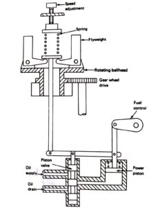
A flyweight assembly is used to detect engine speed. Two flyweights are fitted to a plate or ballhead which rotates about a vertical axis driven by a gear wheel .
The action of centrifugal force throws the weights outwards; this lifts the vertical spindle and compresses the spring until an equilibrium situation is reached. The equilibrium position or set speed may be changed by the speed selector which alters the spring compression.
As the engine speed increases the weights move outwards and raise the spindle; a speed decrease will lower the spindle.
The hydraulic unit is connected to this vertical spindle and acts as a power source to move the engine fuel controls.
A piston valve connected to the vertical spindle supplies or drains oil from the power piston which moves the fuel controls depending upon the flyweight movement. If the engine speed increases the vertical spindle rises, the piston valve rises and oil is drained from the power piston which results in a fuel control movement. This reduces fuel supply to the engine and slows it down. It is, in effect, a proportional controller.
Electric governor
The electric governor uses a combination of electrical and mechanical components in its operation. The speed sensing device is a small magnetic pick-up coil. The rectified, or d.c., voltage signal is used in conjunction with a desired or set speed signal to operate a hydraulic unit. This unit will then move the fuel controls in the appropriate direction to control the engine speed.
